Fundamental Basics: Ohm’s Law
If you can remember V=IR after reading this post, you’ve started building a foundational understanding of electronics.
Without getting deep into theory, history, and discovery, we can summarize that is Ohm’s Law is V=IR, or
Voltage = (current_I) * (resistance_R)
But Joe, what is Voltage, Current, and Resistance, explained to someone without a engineering degree?
- If you recall “potential energy” from elementary grade school science, Voltage defines the electrical potential energy. A typical AAA/AA/C/D battery stores about 1.5 Volts (V) of energy.
- You also probably have an understanding of electrons from grade school science. Electrical Current refers to the flow of electric charge, carried by moving electrons. If you’ve ever had to jump start a car, the transfer of energy from the “good” battery to the “dead” battery is via current. Current is measured in units of Amps (A).
- Resistance describes the difficulty of which electrical current passes though. Resistance is measured in Ohms, typically denoted by (Ω)
These are quite simplified explanations that likely leave out a lot of details, but ideally provide enough information to get going. In the goal of reaching to the widest range of audience, the intent of this blog is to go over enough information to become actionable but point to resources for additional study if desired by the reader.
Ohm’s in the home!
Find (or obtain the following):
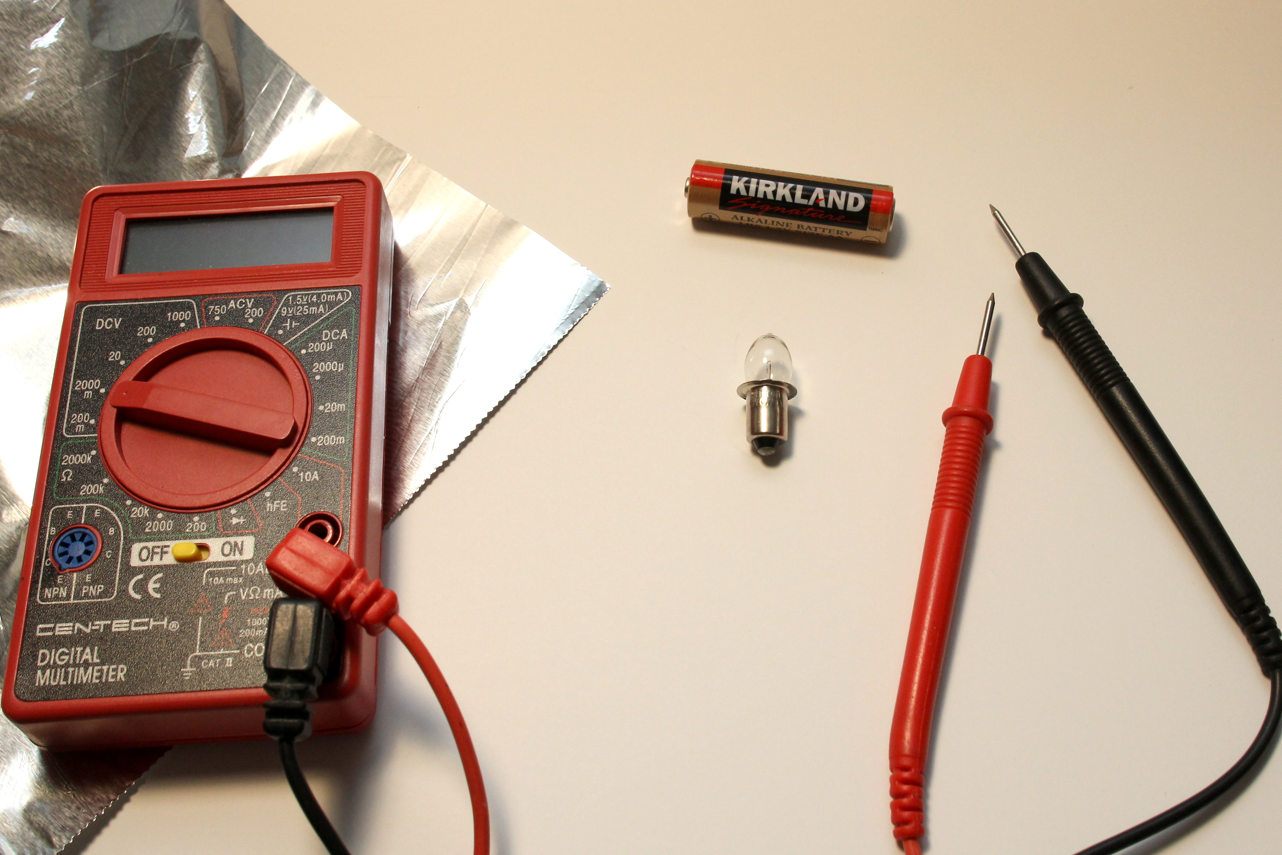
- A non-LED flashlight bulb. If you don’t have one lying around in a miscellaneous drawer, locate a dollar-store or dollar-bin flashlight.
- 1 AA battery.
- Conductive material. This is fancy talk for “wire”. If you don’t have wire, get some aluminum foil.
- Multimeter. We will be measuring resistance, voltage, and current. There might be one in a garage or toolbox. Otherwise, you can find value-priced unit from a Big Box store. Or bring in a “Super Coupon” to a nearby Harbor Freight and pick one up for free to almost free.
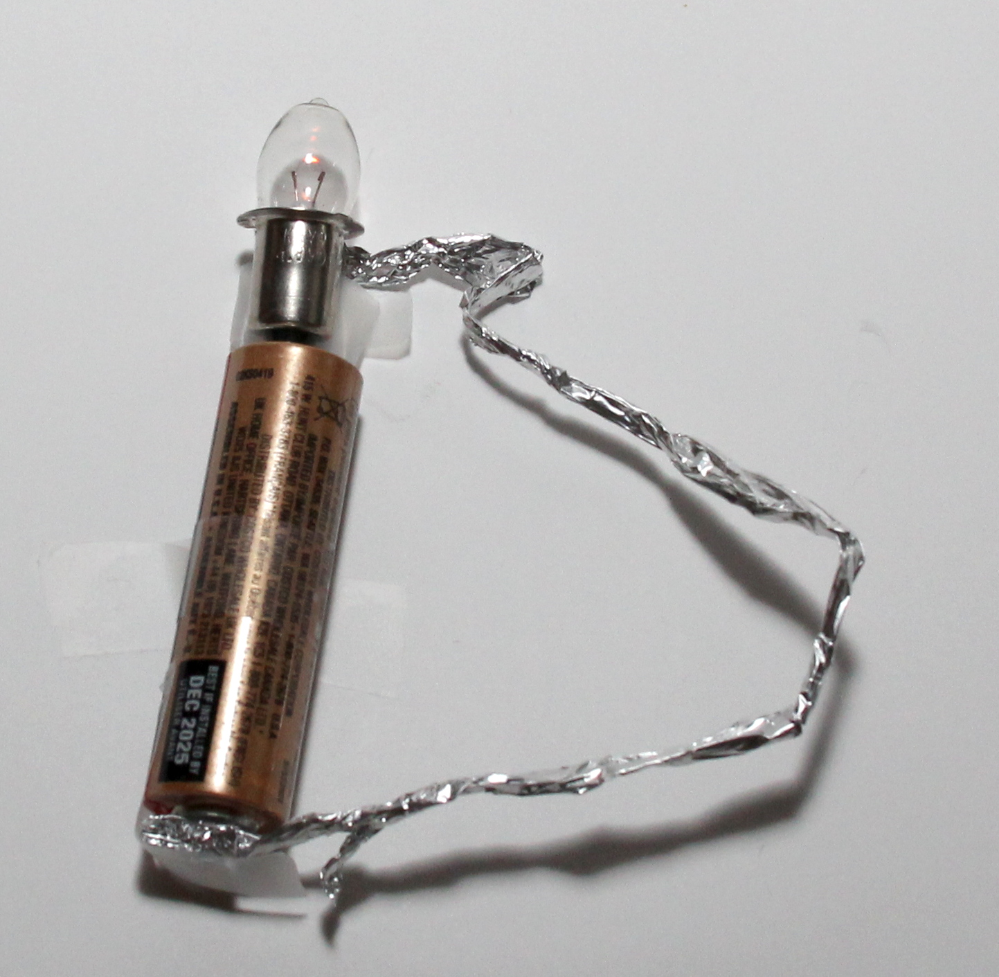
First, check that the flashlight bulb works with the AA battery. We want to make sure the bulb a) is not burned out, and b) can light up with 1 battery. You can do this by placing the butt of the bulb on the (+) side of the battery, and connecting the outer shell of the bulb to the (-) of the battery. Usage of “unidirectional bonding strip” is optional: I’m mainly using tape just to hold things down to take the pictures.
Now, we want to try to measure the resistance of the light bulb. Put your multimeter in resistance mode (look for the Ω). Plug in the black probe to the “COM” socket of the meter, and plug in the red probe to socket with the Ω notation. **In practice, start with the highest resistance range and switch down until the measured resistance value is in range: Put one probe on the bottom of the bulb, and the other on the shell of the bulb. Note the measured resistance value once it settles down.

My bulb, which came from a 6V lantern-battery flashlight, measured about 2.4 Ω. Yours might be different, but as long as you note the value, it’ll be ok.
Now measure the voltage of your AA battery. Put your Multimeter in DC Volts mode. Make sure black probe is plugged into COM and red probe plugged into the socket with the “V” label. Since we know the battery will be around 1.5V, go ahead and select the closet voltage range on your multimeter. To keep the math simple for now, use the smallest range on the dial without the “m” notation (for millivolts) that is at least more than 1.5V.
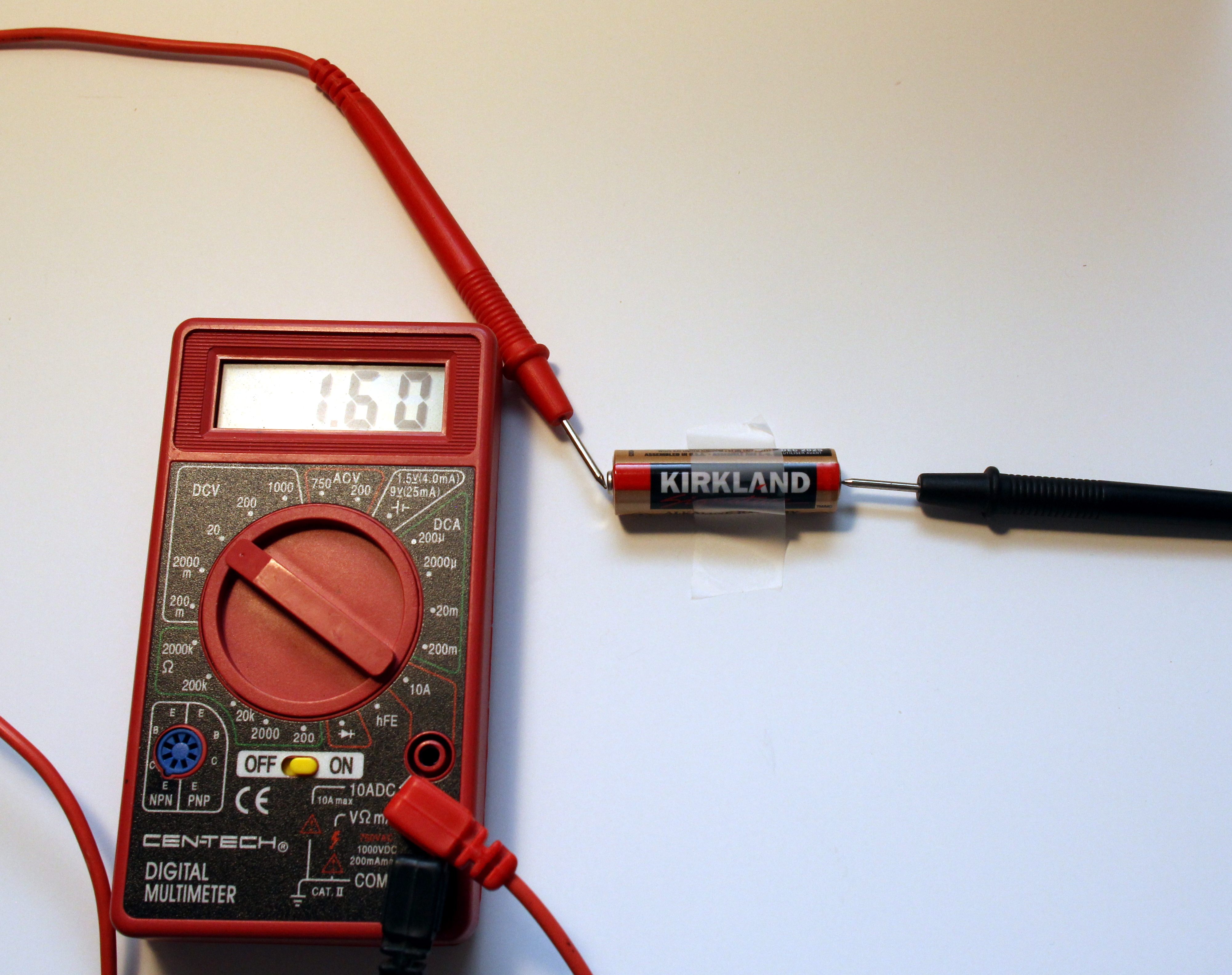
My battery measured 1.60 V. A fresh battery usually measures around 1.6V. Note what yours measures.
A non-LED, filament flashlight has the following circuit:

- The voltage source is the battery (batteries)
- The resistance is the filament light bulb.
- The current is what flows through the wire from the battery, through the bulb, and back into the battery.
With our measured battery voltage and our measured resistance of the flashlight bulb, we can plug-and-chug into Ohm’s Law and calculate the expected current of the flashlight circuit.
V=IR, solve for I:
I = (V / R), or (1.60V / 2.4 Ω) = 0.67 A
We can measure the actual current of our flashlight circuit by using our multimeter in current mode.
Recall from above that current is the flow of energy. Unlike measuring Voltage and Resistance where we measure in parallel with the multimeter, to measure current the multimeter has to be in-line with the circuit, because the current has to flow through the meter to measure it.
Set the dial on your multimeter to current mode (“A”). If there is a choice between “A”, “mA”, and “uA”, select “A”. Plug the red probe to the “A” labeled socket, and plug the black probe to “COM”. Connect the (+) of the battery to the bottom of the light bulb. Hold the red probe to the outer shell of the bulb, and the black probe to the (-) of the battery, thereby completing the circuit with the multimeter in-line. Note the measured current in Amps (A).
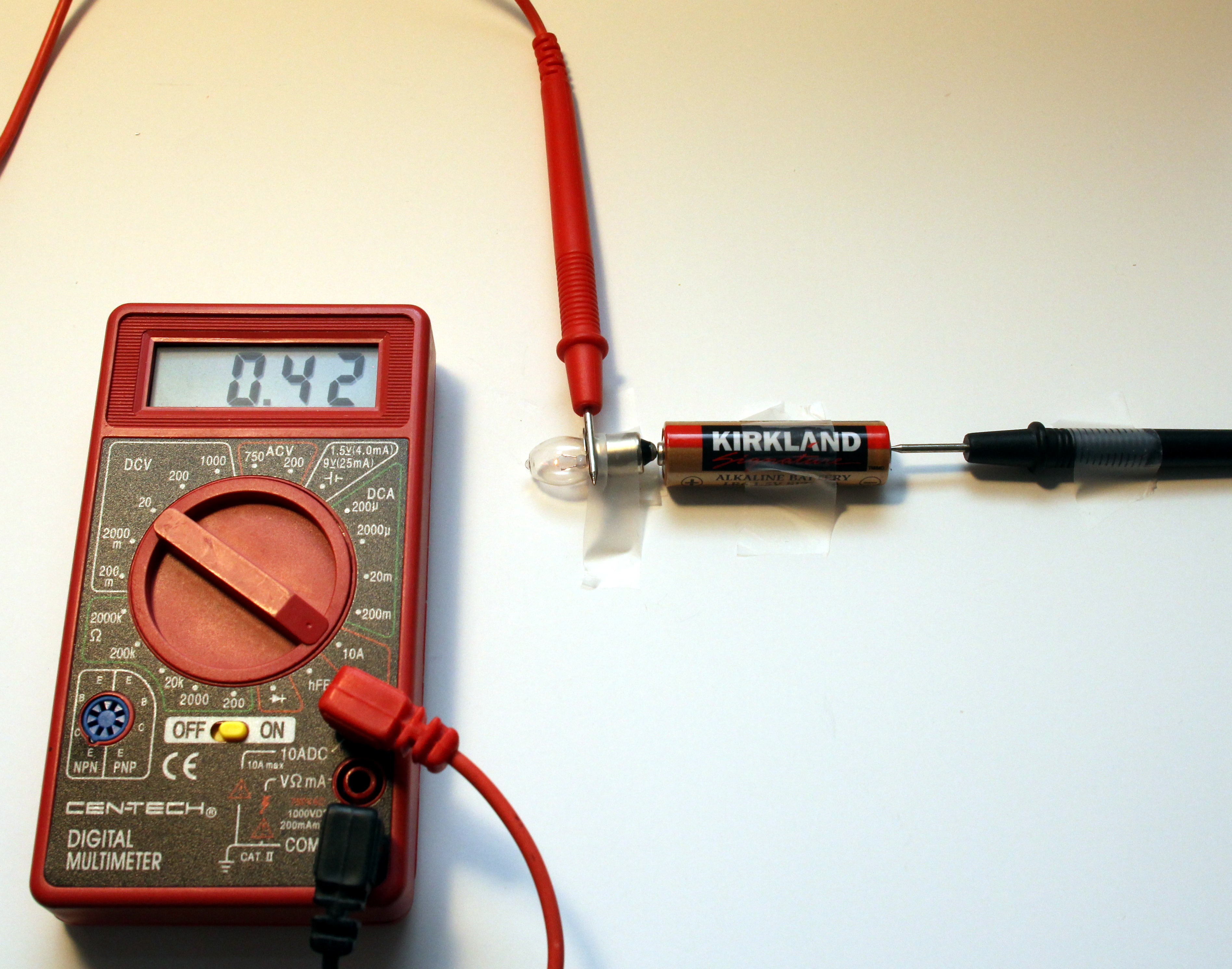
My circuit measured 0.42 A. Close enough. The resistance of the bulb probably changes as its on and heats up, and we measured its resistance when it was “off”. So as long as your measured vs. calculated is within an order of magnitude of each other, we’ll say it’s a success.
Given that: if we want to go off of the actual measured voltage and actual measured current from the circuit in operation, we can go back to Ohm’s law and calculate the resistance of the bulb as it operates in the circuit.
R = (V/I), or (1.60V / 0.42 A) = 3.8 Ω
Application:
Consider your measured current, and assume the bulb resistance (once it lights up) stays the same (you can either use your measured or back-calculated resistance value). Let’s suggest you double the voltage source by using another AA battery. What would you expect the current to be relative to current from using 1 AA battery? (higher, lower, same?)
Calculate out an expected value, and measure the actual current of your flashlight circuit with 2 AA batteries powering the bulb. –Repeat the circuit above, but with the second battery’s (+) placed to the (-) of the first battery, and close the circuit with the multimeter in current mode with the red probe on the bulb shell, and the black probe on the (-) of the second battery.
Again, keep in mind that the bulb resistance will likely change with different supplied voltage. So look for approximate relative difference in current using one battery vs two.
All things considered, ideally I would have written this “lab” to use an actual resistor, but that might keep a lot of readers away from actually trying it out. Finding or obtaining a flashlight bulb to almost represent a resistive load is likely a much easier task than obtaining a 100 Ω through-hole resistor component to someone who didn’t know what a resistor is prior to reading this page. Unfortunately not everyone lives close enough to a Fry’s and Radio Shack is no longer an assumed neighborhood staple.
Further Reading:
One thought on “Fundamental Basics: Ohm’s Law”
Thanks for making it so relatable.