In this episode, we look at the NUCLEO-L152RE to get started on a STM32 platform running FreeRTOS. After following a straightforward set of instructions to bring up the system, we look at demonstrating a use case that benefits from an RTOS (Real Time Operating System) environment.
The NUCLEO-L152RE development board features an ultra-low ARM micro-controller from the STM32L series. The family of NUCLEO boards facilitates evaluation and rapid prototyping with on-board debugging and provides design extensibility via the included Arduino Uno R3 header interface to support integration with off-the-shelf and custom Expansion Shields.
Digi-Key has published a handy guide on getting started with FreeRTOS on the STM32 platform, with a good introduction to the FreeRTOS, briefly discusses where it may be desirable to incorporate an RTOS into a system, and offers specific pointers on getting started with FreeRTOS on the STM32 platform.
Don’t let chip supply chain shortage stop you from building out your hot idea! Pull out that development board hiding in one of your parts bin (or buy one that you can find) and make use of the Arduino Uno R3 header interface! Ask about the Expansion Shield Design Special at JoeLABs!
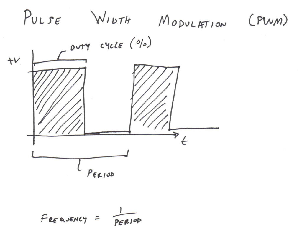
In this episode, we cover the basics of Pulse Width Modulation (PWM), and use an Arduino with quick-and-dirty code as demonstration.
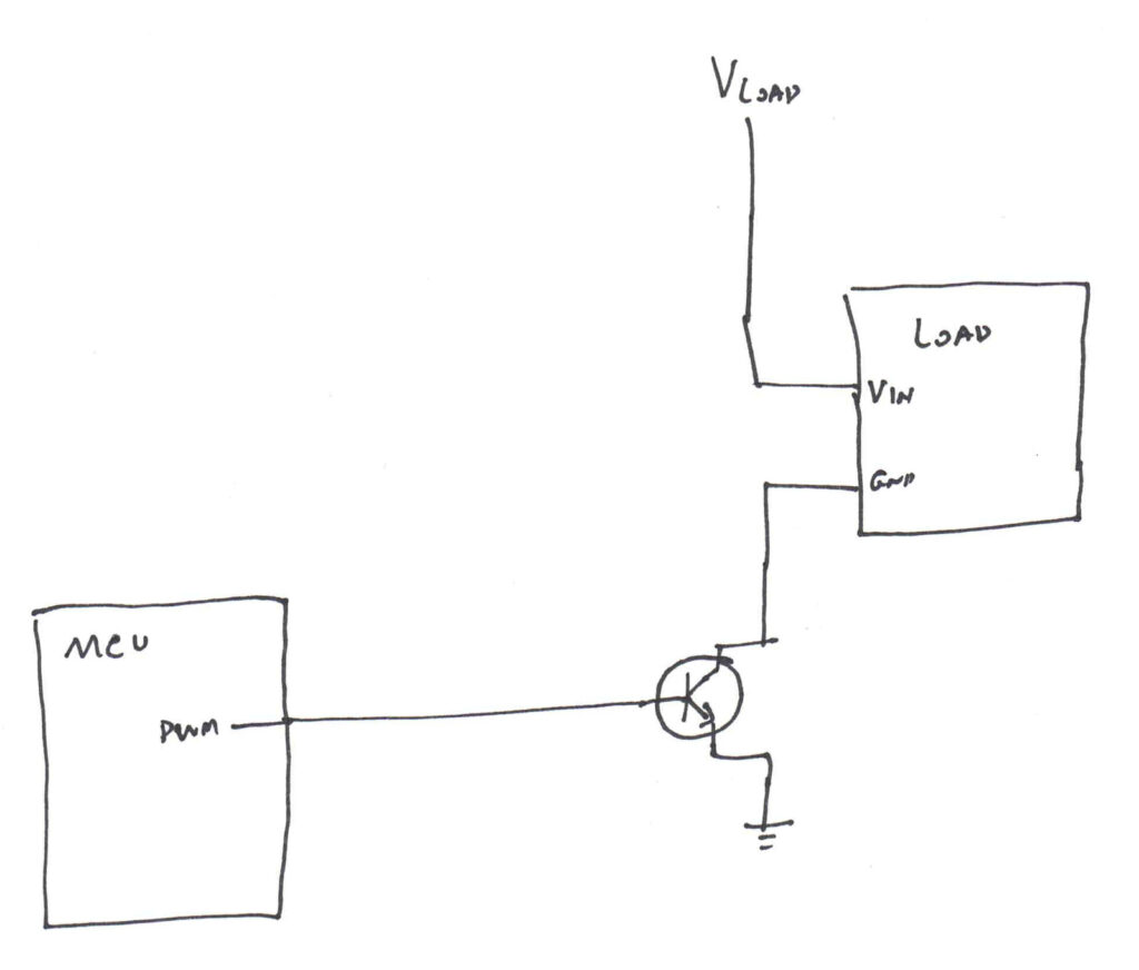
PWM is useful when we need to modulate a load output (e.g. motor, fan, light) that takes in a specific voltage supply, and just lowering the input voltage may not be appropriate or desired.
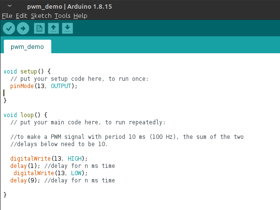
Below is the Arduino sketch featured in the video. I copied this Arduino code from my kids’ schoolwork, because I gave them this same lesson earlier in the school year for (computer) science class.
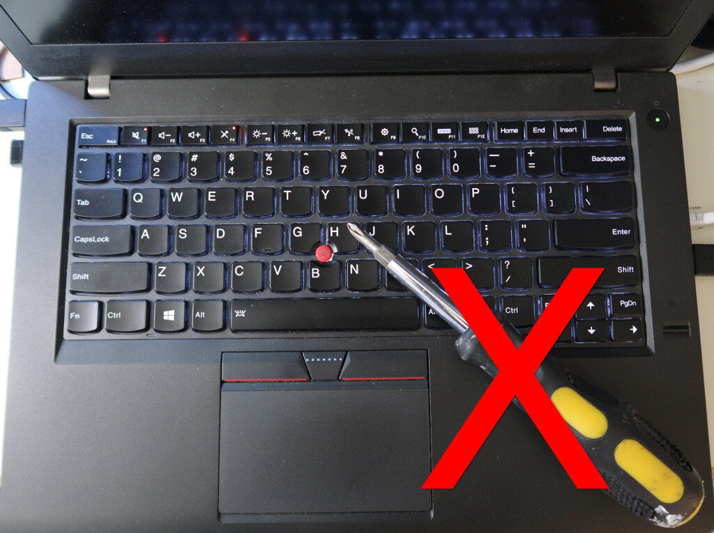
This post’s title question is a quote from Red Hat Linux founder Bob Young, emphasizing the benefit of open source software allowing you to inspect and modify your software tools.
This hood was “welded” shut by the clone tool using GIMP.
Let’s take some creative license with the car analogy.
Would you buy a car that has the battery riveted into the chassis? Let’s say doing so frees up the engine bay a little and allows for a larger battery than the standard cubic 24F battery since its custom shaped into a body member cavity. I would wager most folks would balk at this design choice knowing that batteries expire within a few years and would rather be able to replace the battery without also needing to swap out the front quarter body panel.
Would you buy a car whose engine has the water pump, alternator, A/C compressor, and power steering accessories welded into the engine block instead of conventionally bolted on? While we’re at it, turn them all internal facing so they’re driven by a sealed chain. Let’s propose that permanently fusing these accessories into the engine at the factory nets some performance increase and allows the car designers to shave 3 inches from the engine bay and give that space gain into the passenger cabin. I can almost guarantee someone living in Florida, USA during a humid summer season being told their A/C compressor is broken and has to get a whole new engine put in isn’t going to care as much about the few HP or foot-well room bought by the “fully integrated” engine design.
Now, my examples focus more on the hardware serviceability side of things. But it is important nonetheless because such measures preventing you from maintaining your systems within practical reason have encroached gradually over time with little protesting.
Non-user replaceable batteries have proliferated across most contemporary smartphone offerings, thereby placing a hard limit to use life as service life of Li-Ion batteries is just a few years regardless of use duty. Batteries internally glued to the chassis has been a feature on several higher profile laptop models, making repair a potentially dangerous undertaking.
RAM modules soldered onto the motherboard instead of installed into slots isn’t exactly a new invention — I saw it on a couple lower-end Intel-486 based desktop computers back in the mid-1990s. As those models were marketed for institutional use, my guess is it was due to budgetary reasons. Modern laptops that use soldered RAM will claim it helps thin the chassis (whether or not it matters to the target clientele). Granted, for some slim focused ‘s’ notebooks the tradeoff may be warranted, but is odd when an productivity oriented, unashamed thicker ‘T’ notebook uses soldered RAM. Although RAM failures are quite rare these days, a non-replaceable module is yet another unnecessary system failure point.
Back to my fully integrated engine thought from earlier, soldered RAM (and soldered CPU) may be a non-issue for the appropriate target audience who might be more willing to scrap the entire system of either of those parts started acting up. However, bundling the non-volatile data storage within the weld is asking for trouble no matter the end user. Within such a system, if the main board becomes inoperable for whatever reason (bad power rail, water ingress, exposure to leaked battery acid, etc) the user data is not retrievable. Not only that, SSDs themselves are a consumable component with a finite (although usually long) erase/write life and also not immune to controller silicon failures.
Its easy to envision the not so pleasant future where even though you purchase computing hardware, you really only lease them. The ‘just don’t buy it’ doesn’t always cut it because its not just one offending company, nor is it limited to computer hardware.
The debate on right-to-repair may be promising, but it is a complex discussion with many intricacies that can trip up most legislative bodies who are distracted by the lobbying parties of interest while (hopefully) balancing the reach of government.. Impactful and straightforward, yet non-draconian directives may be hard to come by. How do you go about mandating design for serviceability at the legal level with non-ambiguous verbose? Is it “serviceable” if a board or module can be swapped out, or is the requirement satisfied only with schematics, firmware, and access to vendor specific custom chips?
The mitigation options readily available for preventing computing failure fallout includes redundant data backup/recovery measures, and fallback computing systems at the standby.
I’ve been working on a Bluetooth Low Energy (BLE) based project for the past year, using the Nordic nRF52 integrated SoC. Its powered by a 64MHz ARM Cortex M4 core and Nordic provides good software stack and SDK support.
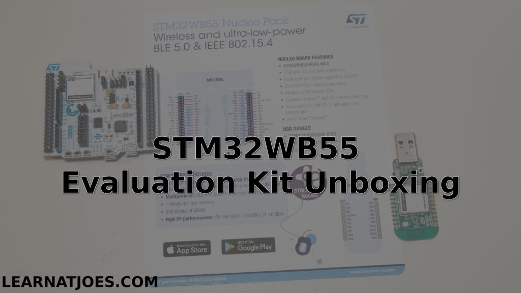
In keeping up with current industry developments, I was excited to hear about a month ago that STMicroelectronics announced their BLE SoC kit: the STM32WB.
I’ve also worked with ST microcontrollers for the past several years, and they also provide good chip level driver library support. The eye-catcher on their BLE chip is that it’s a dual-core design: A 64MHz ARM Cortex M4 to run the application, paired with a 32MHz Cortex M0+ core to run the wireless stack.
After a few weeks of scoping limited inventory, I was able to score an Eval kit:
One of the nice options in working with ARM microcontrollers is that we’re spoiled for choice on IDE options. The Free option is the one I featured today: GNU MCU Eclipse. It is a bit of a setup/install process, but the guide is pretty straightforward and it gets you a $0 development environment that is not feature or code-size limited.
Disclaimer: As an Amazon Associate I earn from qualifying purchases.
Ever since our little ones got hooked on watching NASA/JPL Curiosity landing videos, they’ve developed a strong interest in robotics (yay!!!).
And as luck would have it, our kids would often ask me (the dad) to “build a robot”. When the kids were younger, building models with LEGO would suffice. But it soon became apparent they wanted a “real” machine. I had given a design try a while back. I spent a few evenings looking up design ideas, drafting up sketches of mechanical pieces that we could fab from hobby plywood… but never got further from the computer screen.
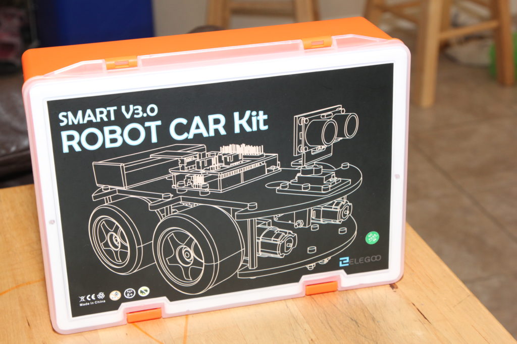
Historically, I haven’t been a huge fan of turnkey kits. I had saw them to be either of low quality or charged a significant premium for the convenience of all pre-selected parts in one box.
The kit comes with an Arduino control board, an I/O board, a ultrasonic module, a bluetooth module, line following module, motors, wheels, chassis, and all hardware needed for assembling the kit.
My Value Justification:
At time of writing, this off-the-shelf kit will get to your door at a reasonable packaged price. You can easily spend half that cost just on machining the chassis plates yourself. You could alternatively individually purchase a standard Arduino board, and other modules, but you’d still have to figure how to mechanically and electrically link them together. The board designs may be open source and be a good EDA design exercise, but good luck getting the PCBs made for < $100 before you even add in the parts BOM.
The Build:
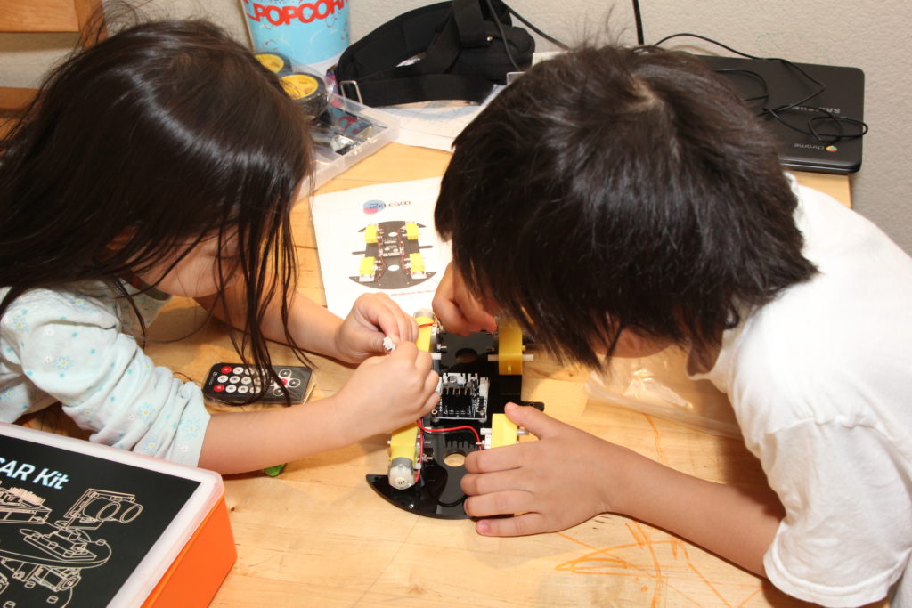
It went really well. The kit came with clear illustrated instructions which our 2nd grader and Kindergartner were able to follow along with just a little hand dexterity help from me for some of the tighter screw assemblies and finer connections.
Parts quality is good. The pieces appear to be machined well. The components and hardware aligned up very easily with little fuss.
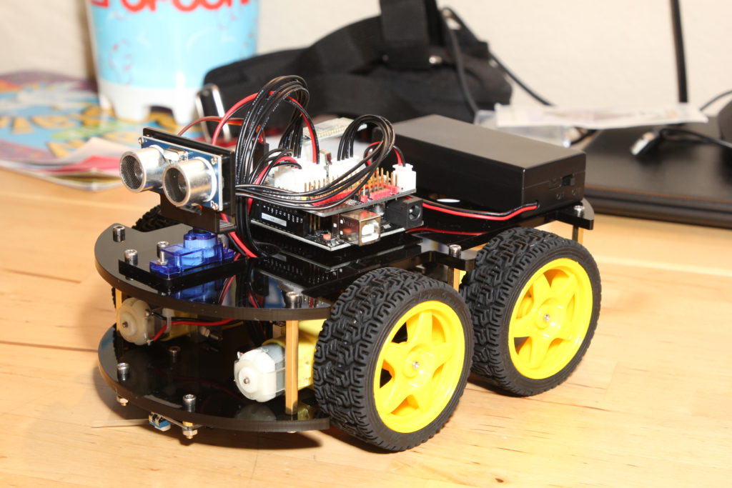
The kids now have a robot:
The kit includes demo and learning firmware projects to load via the Arduino IDE. We are able to upload the “auto_go” firmware to the kit and watch the car drive around on the floor.
I’m quite impressed at this kit, what it comes with, and what it enables. The car robot as-kitted presents many learning applications, but it also lends itself to expansion and modding.
In terms of inspiring learning pursuits, robotics engages the young hungry minds in mechanical engineering, electronics design, embedded firmware development, and applications development.
Disclaimer: As an Amazon Associate I earn from qualifying purchases
Throughout the school year we introduce computer science concepts as appropriate for age and skill level. Towards the end of last school year we started using the micro:bit platform as a fun learning tool with much success and plan to continue in the following weeks.
The micro:bit is a plug-and-go easy to use introductory electronics and programming platform with a 5×5 LED “display” matrix, a couple buttons, and a 3-axis accelerometer.
The kit comes with a battery pack and a short micro-USB cable for power/programming. The longer hi-visibility red cable that I used is this one: https://amzn.to/2KQv6Wm
The programming environment is web based, so any computer with a modern browser and an available USB port should work. Our kids were able to do the labs with our relatively low-power, long battery life Chromebook
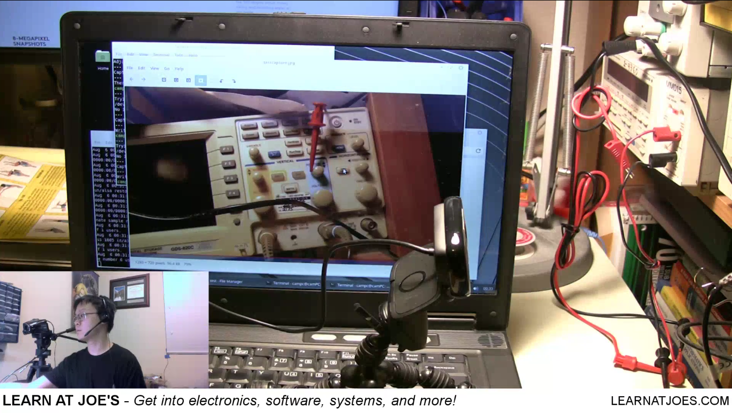
Time-Lapse capture with webcam and Linux scripting.
Disclaimer: As an Amazon Associate I earn from qualifying purchases.
Time-lapse photography is a concept of taking snapshots at a particular interval over time to record events in a low resource manner, compared to capturing a video stream. Here, we discuss how to use a relatively inexpensive web camera and a computer to build a low-budget time-lapse platform.
Action Summary
Video capture of a video capture
Pretty much any relatively modern PC with decent storage and functional USB 2.0 ports should suffice. I had an old big-box special on hand.
Logitech webcams tend to plug-and-play easily with Linux distros:
The Logitech C615 is the model featured. It does 1080p capture, with some nudging.
*Even though I held up an external HDD in the footage, I didn’t get to show setting that up yet and instead relying on internal storage for now.
We looked at how to use the fswebcam Command Line utility to capture images via the terminal. You may either git clone from the project page, or on an Ubuntu/Mint system, enter in a terminal window:
sudo apt-get install fswebcam
It is a bit of trial-and-error figuring the optimal parameters for the fswebcam utility with a camera.
Then we watched how bad I am at live shell scripting, though I freely admit its not my everyday gig and that I make liberal use of internet search the few times I write shell scripts. Can’t go wrong with an O’Reilly book on Shell Scripting if you want an at arms reach reference to thumb through
Hope you found this useful and informative. Having a setup like this opens up a lot of other potential applications to build upon.
Disclaimer: from a technical and functional perspective, this post is about using extending usage of commodity hardware using computer scripting. There are some potential premise security applications for such a setup. While anyone is welcome to use the information herein, the reader is responsible for determine appropriate for use, deployment, and maintenance of such applications for their security needs. I/We do not explicitly endorse this type of setup as a part of a security protocol.
One of the “wink and nod” policies among engineering and IC companies is the free samples of parts. Many chip manufacturers have such policies in place for a lot of their parts. My favorite standbys have been:
I’m sure there’s other manufacturers with comparable samples programs. The motivation of the companies offering sample parts for you (the designer, whether professional or student) is that once you’re familiar with the part, you or your company’s purchasing department is likely to issue a PO for quantity of their parts for a build.
As a (hungry) student, this is great for sourcing parts for a project, because let’s face it: every penny counts. It also doesn’t hurt that the samples ship free, and sometimes ship really fast (e.g. TI).
Even when working with a company who has a DigiKey account and a FedEx account, manufacturer free samples can sometimes be less of a hassle to get 1 or 2 parts, than bothering the office administrator to put in an order.
My general notes for free samples:
Please don’t abuse the system. Only sample parts you’ll actually use, and limit to evaluation or at most 1 test build. After that, support the company and legitimately purchase parts. Don’t ruin this for every one else.
Create an account with each company you wish to sample from.
Most (if not all) IC companies companies won’t sample with a general free email account, such as @gmail and @yahoo.
Instead, if you have a domain, use an email address with that. Or use your school’s student email if you have one.
Failing those options, use your work’s email address if you believe it’s within your company’s acceptable use to do so. Frankly, I can’t see why a company would be against your professional career development, but if they have a cow with you using their email to get free IC samples, maybe its time to look elsewhere for growth.
Most IC companies do limit quantities and number of orders within some time, so plan judiciously.
If you do get a contact from a sales rep, take it as an invitation to share what you’re learning or working on (within reason, especially if through an employer). They can be a good resource for parts information and support.
With industry mostly standardizing on surface mount parts, finding parts, much less those available for sample, in Dual In-Line Package (DIP) for your breadboards are getting harder to find. But they are still there. Just be sure you select the correct packaging for your sample orders. Fallback is to order the surface mount parts (e.g. SOIC, TSOP…) and get a breakout board that you can solder the part onto, and the board runs the lines to more accessible headers. –or if you’re really good just solder thin wires to the part legs.
Disclaimer: As an Amazon Associate I earn from qualifying purchases
Learning about electronics with just paper and pencil only goes so far. Eventually it’s really nice to get your hands on actual electronic parts.
It used to be that if you were near a mall, you could walk into a Radio-Shack and come out with electronic components. If you’re more fortunate, you can also get a good selection from a Fry’s Electronics.
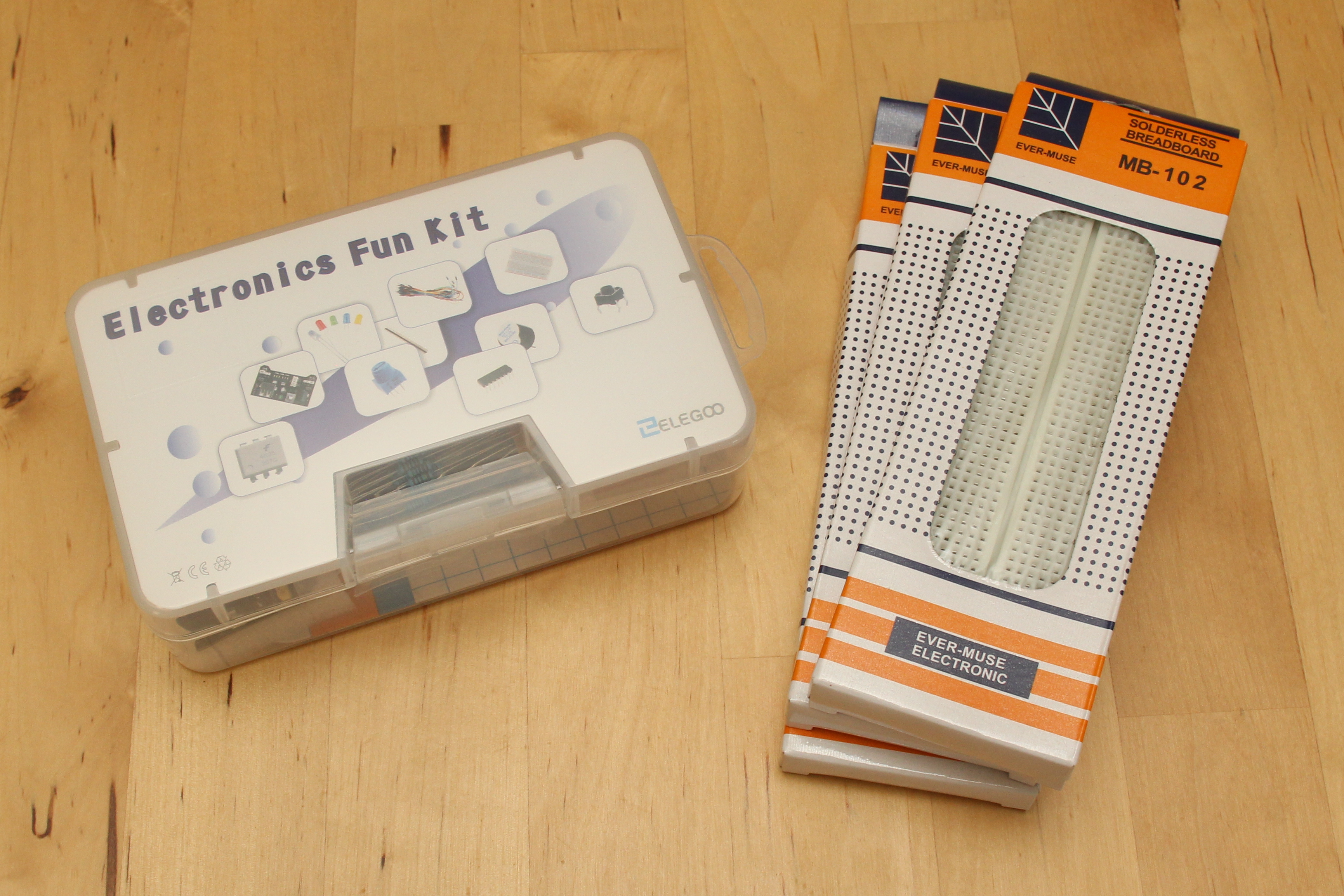
I got an electronics kit, aptly named “Electronics Fun Kit”, as well as a few extra breadboards. I’ll use this to stage workshops and other posts on this site. As well as introducing electronics to our kids as part of Science.
Amazon is an almost-universally accessible online retailer, hence the vendor of choice today. Other sites like DigiKey are quite good, but are also easy to get lost for a novice.
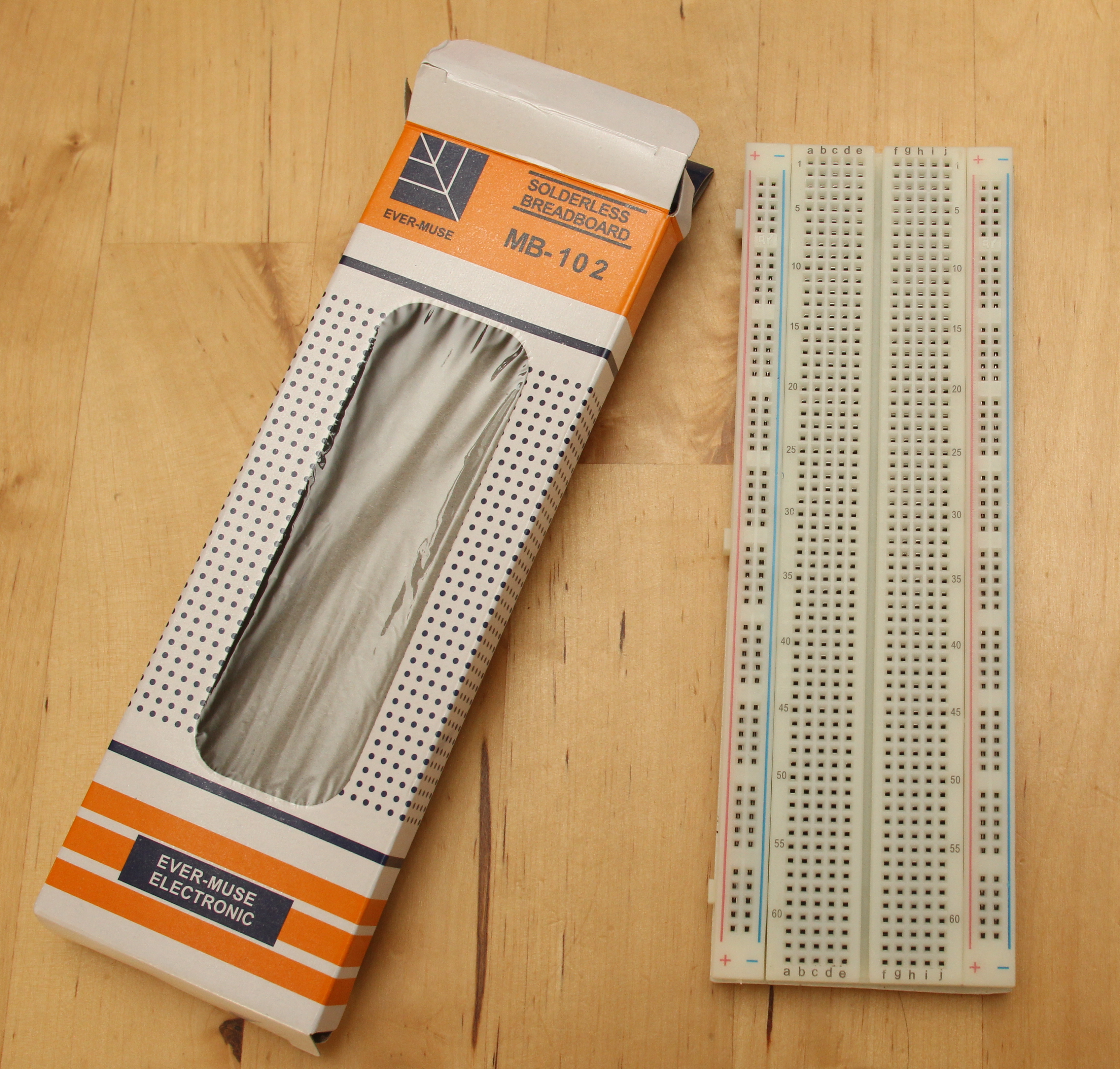
The 3-pk of Elegoo MB-102 Breadboard is as expected for a breadboard. A breadboard is an easy electronics prototyping platform for through-hole components and solder-less wires.
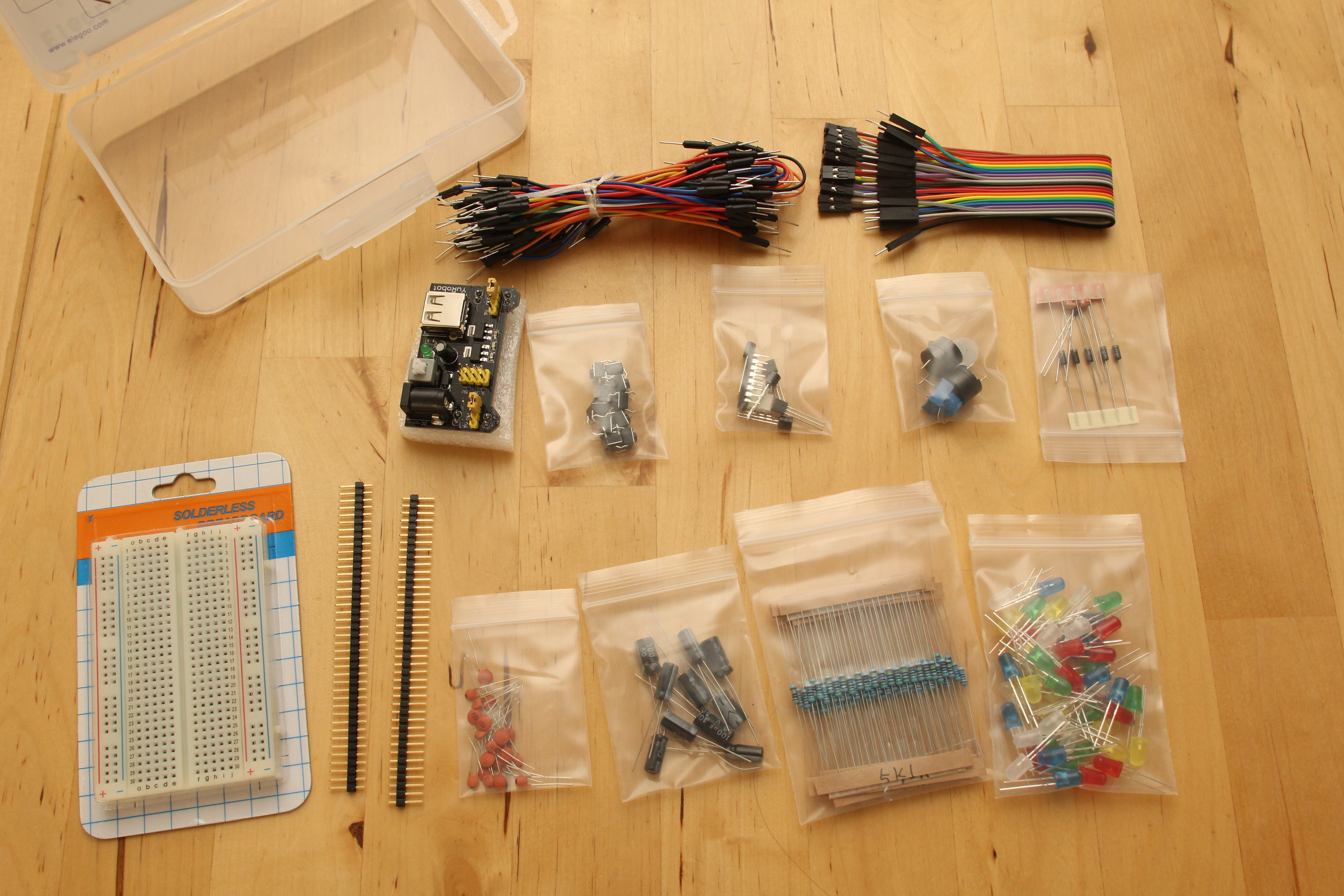
The Elegoo EL-CK-002 Electronic Fun Kit Bundle comes with a sample of LEDs, caps, resistors, diodes, buttons, jump wires, header pins, pretty much anything you’d need to get started:
When I ordered it, I wasn’t sure of the included power board and thought it’d be rubbish. But in checking it out, it looks to be a convenient USB-to-Power supply with an ON/OFF switch to boot!
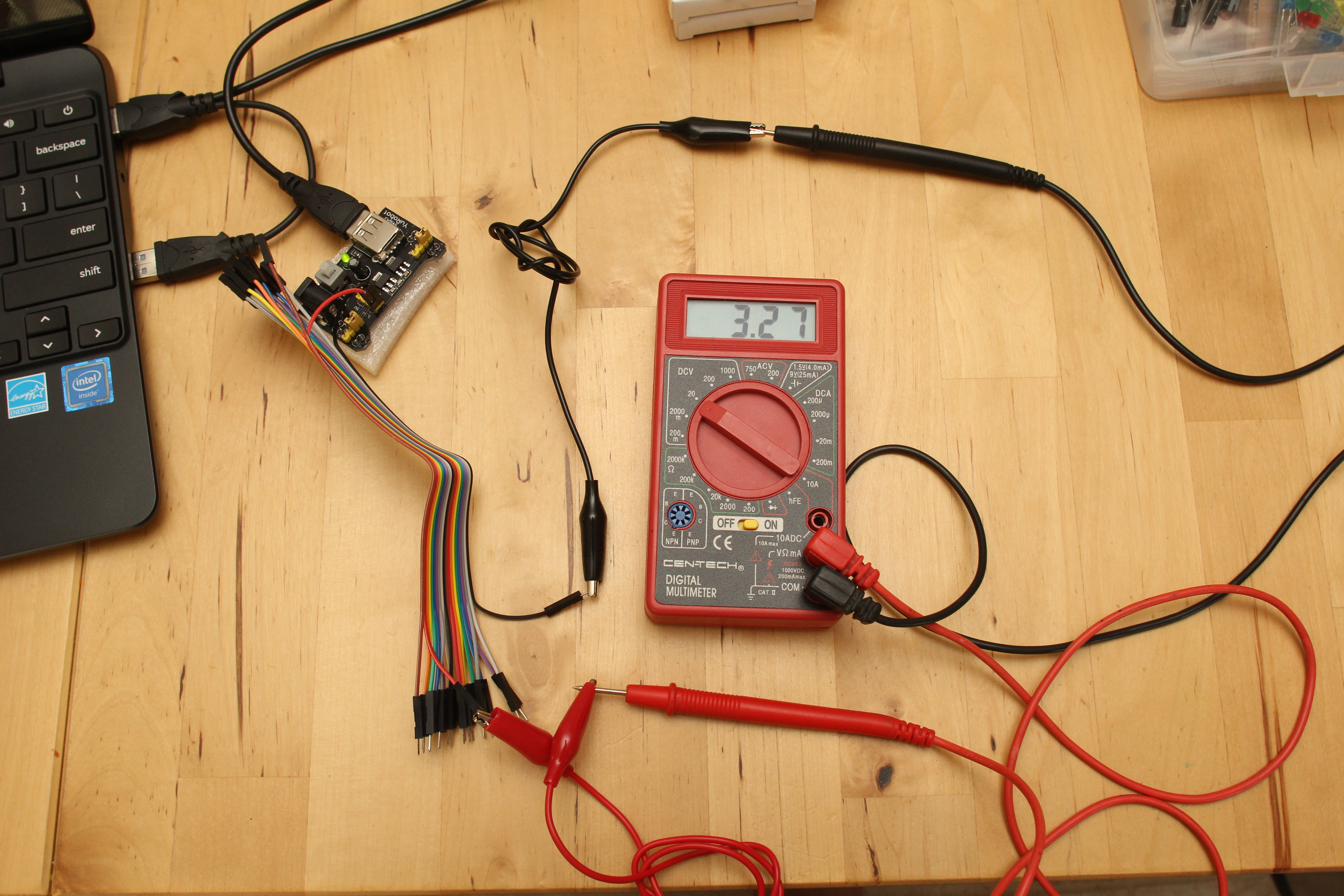
Here the board is taking in +5 VDC from a USB port, and outputting ~3.3v. The board also accepts input power from a DC barrel.
Having this board available makes it easier to power a circuit without calling out a separate regulator circuit. I’ll have to check the specs on the on-board regulators (there’s no documentation) but conceivably 4 AA batteries(6V) could be rigged thru a DC barrel or USB plug for untethered operation.
All in all, this looks to be a promising startup kit/
If you can remember V=IR after reading this post, you’ve started building a foundational understanding of electronics.
Without getting deep into theory, history, and discovery, we can summarize that is Ohm’s Law is V=IR, or
Voltage = (current_I) * (resistance_R)
But Joe, what is Voltage, Current, and Resistance, explained to someone without a engineering degree?
If you recall “potential energy” from elementary grade school science, Voltage defines the electrical potential energy. A typical AAA/AA/C/D battery stores about 1.5 Volts (V) of energy.
You also probably have an understanding of electrons from grade school science. Electrical Current refers to the flow of electric charge, carried by moving electrons. If you’ve ever had to jump start a car, the transfer of energy from the “good” battery to the “dead” battery is via current. Current is measured in units of Amps (A).
Resistance describes the difficulty of which electrical current passes though. Resistance is measured in Ohms, typically denoted by (Ω)
These are quite simplified explanations that likely leave out a lot of details, but ideally provide enough information to get going. In the goal of reaching to the widest range of audience, the intent of this blog is to go over enough information to become actionable but point to resources for additional study if desired by the reader.
Ohm’s in the home!
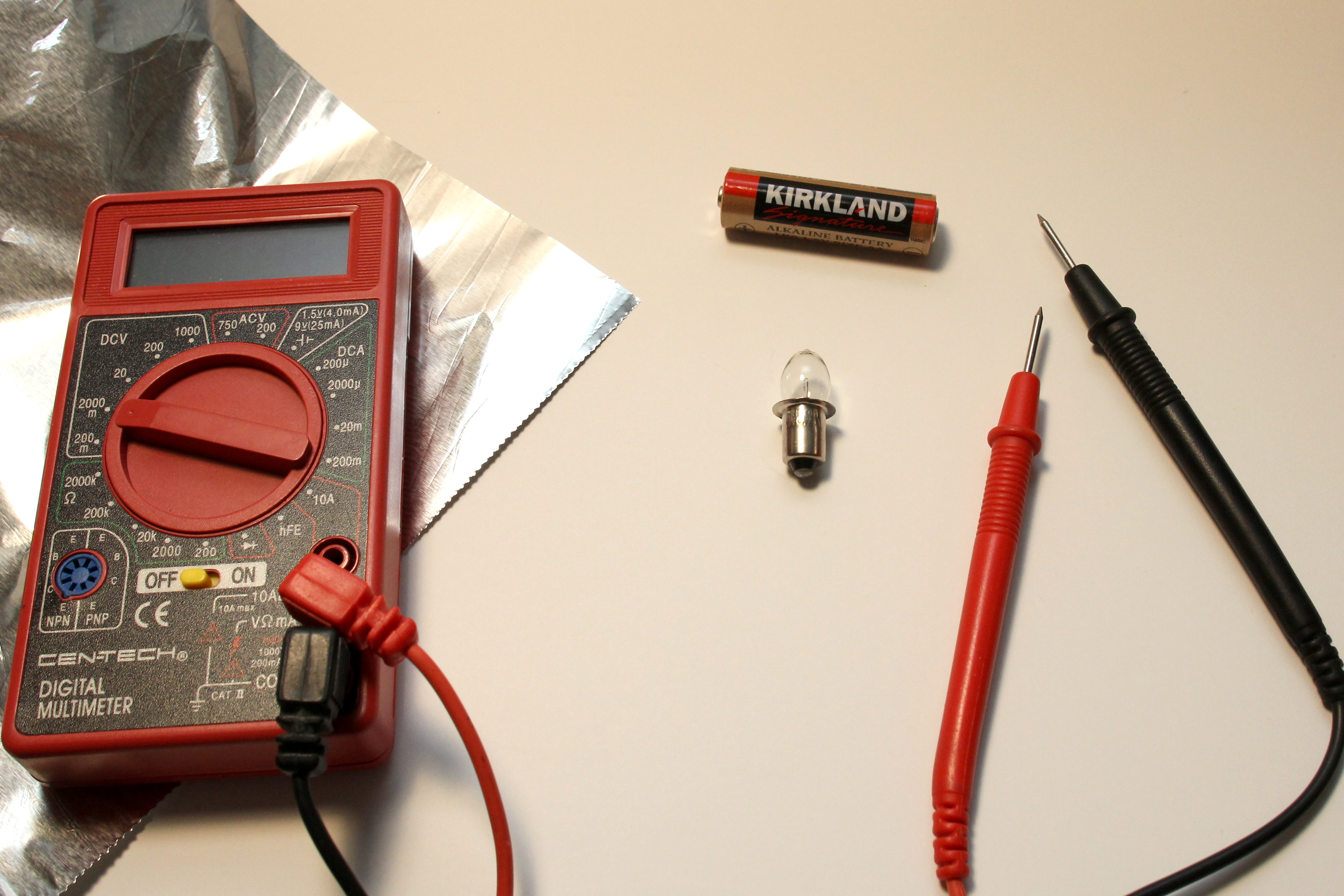
Find (or obtain the following):
A non-LED flashlight bulb. If you don’t have one lying around in a miscellaneous drawer, locate a dollar-store or dollar-bin flashlight.
1 AA battery.
Conductive material. This is fancy talk for “wire”. If you don’t have wire, get some aluminum foil.
Multimeter. We will be measuring resistance, voltage, and current. There might be one in a garage or toolbox. Otherwise, you can find value-priced unit from a Big Box store. Or bring in a “Super Coupon” to a nearby Harbor Freight and pick one up for free to almost free.
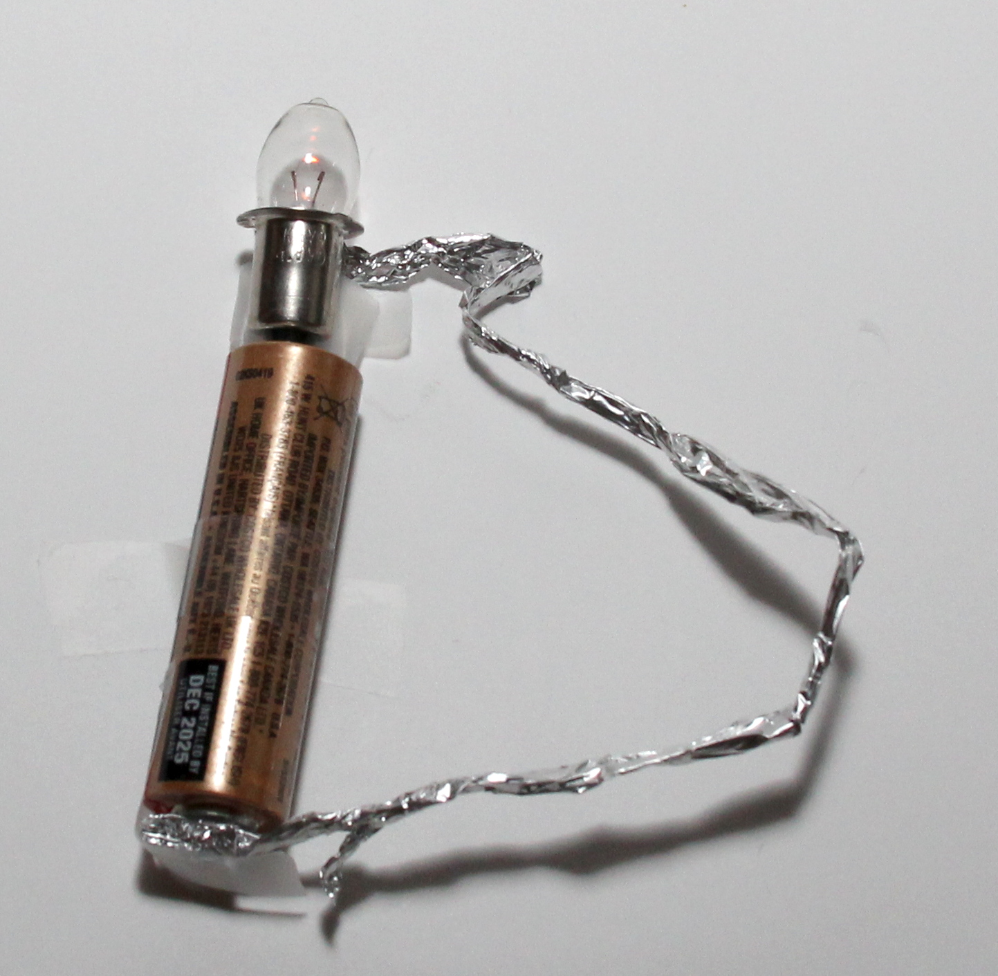
First, check that the flashlight bulb works with the AA battery. We want to make sure the bulb a) is not burned out, and b) can light up with 1 battery. You can do this by placing the butt of the bulb on the (+) side of the battery, and connecting the outer shell of the bulb to the (-) of the battery. Usage of “unidirectional bonding strip” is optional: I’m mainly using tape just to hold things down to take the pictures.
Non-insulated conductor is generally frowned upon, but this is really low voltage/current so we’re ok here for now.
Now, we want to try to measure the resistance of the light bulb. Put your multimeter in resistance mode (look for the Ω). Plug in the black probe to the “COM” socket of the meter, and plug in the red probe to socket with the Ω notation. **In practice, start with the highest resistance range and switch down until the measured resistance value is in range: Put one probe on the bottom of the bulb, and the other on the shell of the bulb. Note the measured resistance value once it settles down.
My bulb, which came from a 6V lantern-battery flashlight, measured about 2.4 Ω. Yours might be different, but as long as you note the value, it’ll be ok.
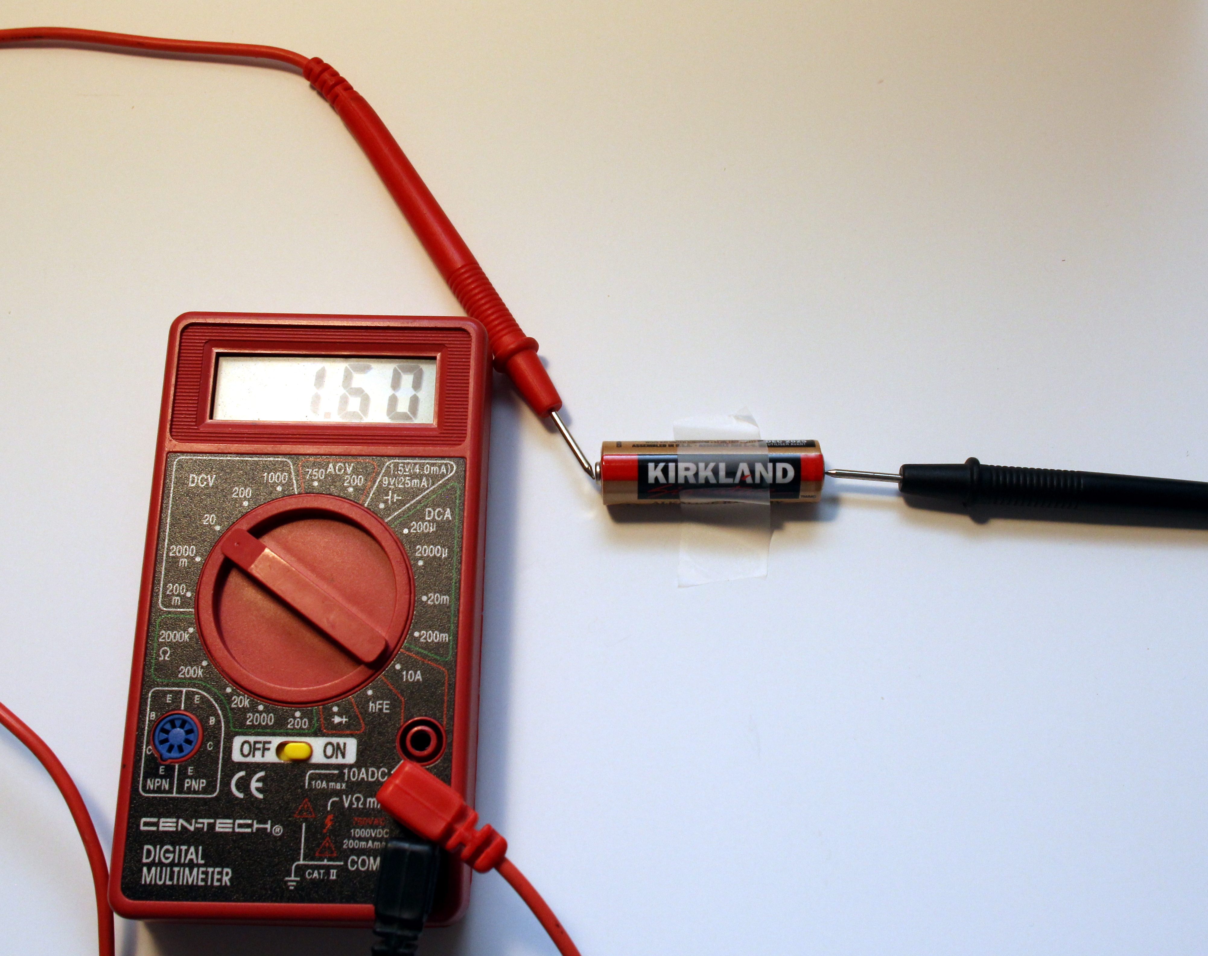
Now measure the voltage of your AA battery. Put your Multimeter in DC Volts mode. Make sure black probe is plugged into COM and red probe plugged into the socket with the “V” label. Since we know the battery will be around 1.5V, go ahead and select the closet voltage range on your multimeter. To keep the math simple for now, use the smallest range on the dial without the “m” notation (for millivolts) that is at least more than 1.5V.
My battery measured 1.60 V. A fresh battery usually measures around 1.6V. Note what yours measures.
A non-LED, filament flashlight has the following circuit:
The voltage source is the battery (batteries)
The resistance is the filament light bulb.
The current is what flows through the wire from the battery, through the bulb, and back into the battery.
With our measured battery voltage and our measured resistance of the flashlight bulb, we can plug-and-chug into Ohm’s Law and calculate the expected current of the flashlight circuit.
V=IR, solve for I:
I = (V / R), or (1.60V / 2.4 Ω) = 0.67 A
We can measure the actual current of our flashlight circuit by using our multimeter in current mode.
Recall from above that current is the flow of energy. Unlike measuring Voltage and Resistance where we measure in parallel with the multimeter, to measure current the multimeter has to be in-line with the circuit, because the current has to flow through the meter to measure it.
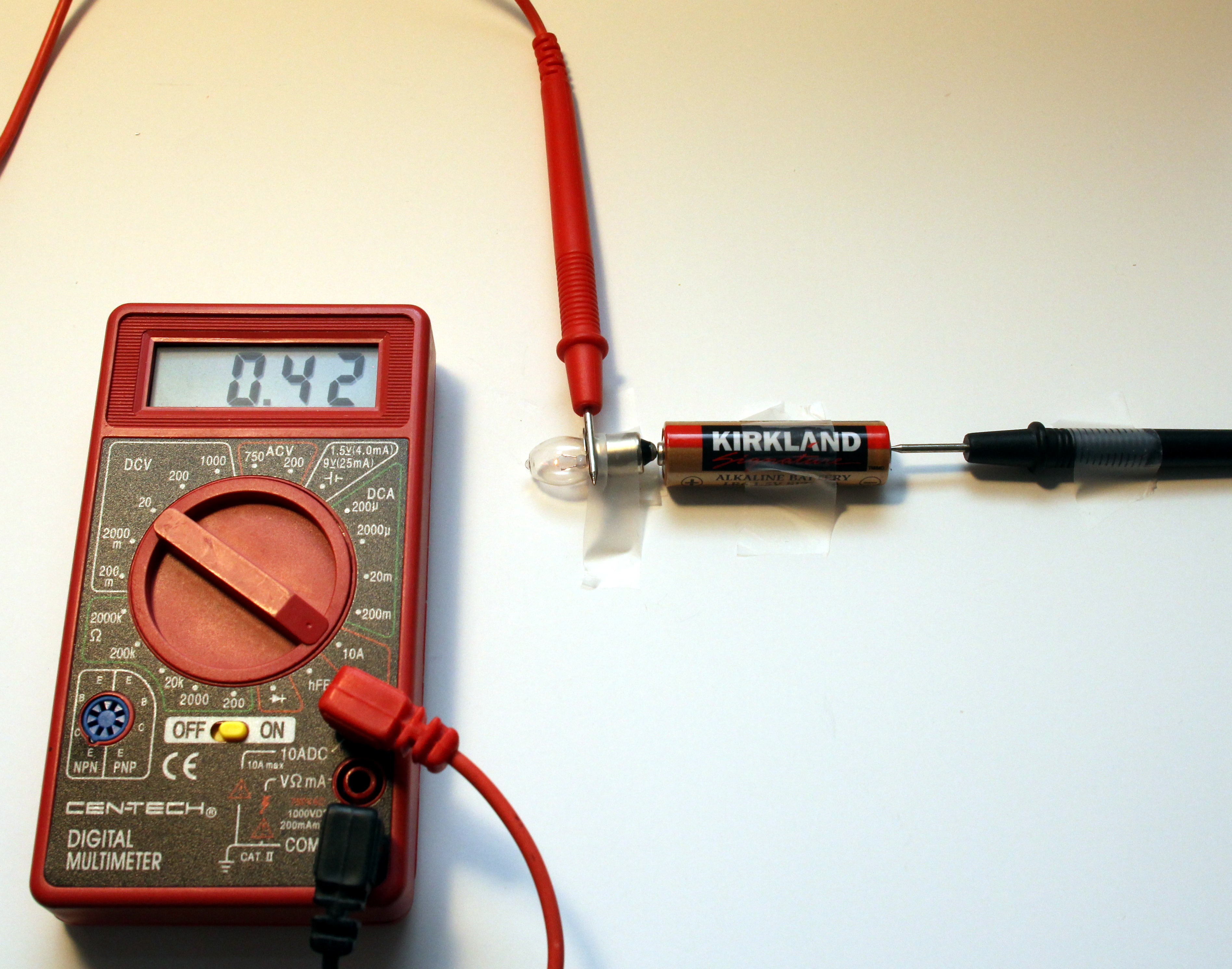
Set the dial on your multimeter to current mode (“A”). If there is a choice between “A”, “mA”, and “uA”, select “A”. Plug the red probe to the “A” labeled socket, and plug the black probe to “COM”. Connect the (+) of the battery to the bottom of the light bulb. Hold the red probe to the outer shell of the bulb, and the black probe to the (-) of the battery, thereby completing the circuit with the multimeter in-line. Note the measured current in Amps (A).
My circuit measured 0.42 A. Close enough. The resistance of the bulb probably changes as its on and heats up, and we measured its resistance when it was “off”. So as long as your measured vs. calculated is within an order of magnitude of each other, we’ll say it’s a success.
Given that: if we want to go off of the actual measured voltage and actual measured current from the circuit in operation, we can go back to Ohm’s law and calculate the resistance of the bulb as it operates in the circuit.
R = (V/I), or (1.60V / 0.42 A) = 3.8 Ω
Application:
Consider your measured current, and assume the bulb resistance (once it lights up) stays the same (you can either use your measured or back-calculated resistance value). Let’s suggest you double the voltage source by using another AA battery. What would you expect the current to be relative to current from using 1 AA battery? (higher, lower, same?)
Calculate out an expected value, and measure the actual current of your flashlight circuit with 2 AA batteries powering the bulb. –Repeat the circuit above, but with the second battery’s (+) placed to the (-) of the first battery, and close the circuit with the multimeter in current mode with the red probe on the bulb shell, and the black probe on the (-) of the second battery.
Again, keep in mind that the bulb resistance will likely change with different supplied voltage. So look for approximate relative difference in current using one battery vs two.
All things considered, ideally I would have written this “lab” to use an actual resistor, but that might keep a lot of readers away from actually trying it out. Finding or obtaining a flashlight bulb to almost represent a resistive load is likely a much easier task than obtaining a 100 Ω through-hole resistor component to someone who didn’t know what a resistor is prior to reading this page. Unfortunately not everyone lives close enough to a Fry’s and Radio Shack is no longer an assumed neighborhood staple.