Browsed by
Category: Software

STM32 + FreeRTOS on NUCLEO-L152RE

STM32 + FreeRTOS on NUCLEO-L152RE

STM32 + FreeRTOS on NUCLEO-L152RE

In this episode, we look at the NUCLEO-L152RE to get started on a STM32 platform running FreeRTOS. After following a straightforward set of instructions to bring up the system, we look at demonstrating a use case that benefits from an RTOS (Real Time Operating System) environment.

The NUCLEO-L152RE development board features an ultra-low ARM micro-controller from the STM32L series. The family of NUCLEO boards facilitates evaluation and rapid prototyping with on-board debugging and provides design extensibility via the included Arduino Uno R3 header interface to support integration with off-the-shelf and custom Expansion Shields.

Digi-Key has published a handy guide on getting started with FreeRTOS on the STM32 platform, with a good introduction to the FreeRTOS, briefly discusses where it may be desirable to incorporate an RTOS into a system, and offers specific pointers on getting started with FreeRTOS on the STM32 platform.

The JoeLABs Expansion Shield Special!

Don’t let chip supply chain shortage stop you from building out your hot idea! Pull out that development board hiding in one of your parts bin (or buy one that you can find) and make use of the Arduino Uno R3 header interface! Ask about the Expansion Shield Design Special at JoeLABs!

LPT: If you’re using a computer for work, One is None

LPT: If you’re using a computer for work, One is None

About a year ago I had a conversation with a professional friend about our work arrangements at the time, and what we’d do in terms of bench setup if we each were to do full-time independent consulting and contracting. Almost immediately we unanimously agreed on having two (2) computers.

The rationale is pretty obvious: loss of use of computing tools for design and development is a major risk to revenue when you’re the invoicing party. However, being stuck in the water when your only corporate issued rig gives up isn’t fun either.

I was reminded of that think-storm session earlier this week, right in the middle of a rather intense sprint.

Fortunately, it’s still able to boot after entering Startup Settings and toggling an option. But I have to do it every time now.

Luckily, this halting-on-boot laptop wasn’t the only computer I have for development, because otherwise it would have been very inconvenient in the project support, and a potentially major hassle should major servicing be required during COVID-19 shelter-in-place.

I experienced no loss to productivity because I perform most development with another computer that is my daily driver. On the table next to it is my secondary computer, which while not identically configured, can stand in with the same tool chains should need arise.

Of course, a sound data backup and recovery plan is always necessary and most people (hopefully) have that in mind, especially as some computer models tightly integrate storage modules rendering recovery difficult when the system fails to operate. Redundancy in workstations and other important tools may not often be in the forefront of thought, but is an important consideration. Even if you’re able to pick-up a new computer from the store within the hour, it may take a day or so to load up your software tools to get back to being productive.

It took me a few months to determine the most appropriate redundant systems strategy. At first, I had thought of keeping two mostly identical computers but realized quickly that one of them would most likely collect dust. Two exact setups are also potentially vulnerable to same-time failure if for example, the OS vendor pushes out a faulty automatic update.

I presently settled upon maintaining complementary platforms that are able to either host cross-platform tools natively and/or virtualize operating environments that can be replicated. This way, the computer resources all get utilized on a regular basis and have enough overlap should one fail at an inopportune time.

Getting Python to Play the Piano

Getting Python to Play the Piano

Disclaimer: As an Amazon Associate I earn from qualifying purchases

During a recent visit to Costco, the kids and I walked past the KAWAI pianos on roadshow display. We were admiring one of the models that was fully acoustic on the instrument side, but had some embedded electronics and firmware that automated music playing by mechanically actuating the keys.

The nice sales gentleman made his pitch that it’s value in entertaining without requiring an actual piano player. The model on display was $18,999. Considering that I look like a broke college kid most days and our cart contained other low-cost items, I’m hoping the sales gent was being somewhat joking in a deadpan manner and not expecting us to actually place an order on the spot. Plus, I had earlier remarked to my daughter that the price of the piano was just as much as my daily driver sedan.

But it got me to recall that our more modest digital piano is equipped with a USB (USB to Host) port. I was able to confirm after quick documentation review that the USB port presents itself as a MIDI device. I found a USB A/B cable and attached it to the nearby Linux laptop. The OS detected it just fine without requiring any additional drivers or manual kernel module loading.

To anyone at Yamaha reading this, THANK YOU for building devices with standard interfaces without requiring proprietary software or connectivity hardware. For that, you rock.

I spent the next few days downloading MIDI files of various popular music arranged by random folks, and piped them to the piano for play-by-instrument using Rosegarden, which is a music composing and editing program. How well a song performs depends on the arrangement, and the nature of the song’s genre contributes as well. (popular 90s era Latin Pop/Dance sound amazing)

For those unfamiliar: compared to a sound file (.wav) that contains a pulse-code sequence to represent a audio signal, a MIDI file is essentially a sequence of instructions to command an instrument device (physical, or software emulation) to play notes/sounds with prescribed voice and other parameters as well as set instrument controls.

But in my quest for semi-unattended playback, I wanted something that I could just load a playlist and go. I didn’t find such a program, so I went ahead and drafted up a Python script.

The relatively basic script scans the directory for MIDI files into an array, randomly sorts the array, and then calls ‘aplaymidi’ program that comes with Linux with the MIDI port number and file name to play. It features some filename character escaping and very little robust error case handling. But it does catch CTRL+C to gracefully (as best it can) quit out of the loop.

The script runs on the laptop as expected. But because it’s Linux + Python, it also runs on a Raspberry Pi.

I had a moment of pause wondering if the plug-and-play would indeed work on the Pi since it’s ARM based vs. x86/x64, but it was for not because it detected just fine.

Here’s the script running on the Pi, invoked from an SSH terminal shell, since I’m running the pi headless (no monitor or keyboard/mouse attached)

It is truly amazing that I can attach a $35 computer and “upgrade” a lower cost instrument with feature(s) found on models costing hundreds or thousands more!

With the GPIO pins on the RPi, I could certainly attach some hardware buttons and handle events for Play/Stop, FF, and Prev. –For another time, or I’ll leave it as an exercise for you the reader.

Addendum: As with most software projects, the same objective could have been accomplished with other solutions (in this case: shell script, perl, etc) but 1) I wanted to expand my python-fu, and 2) Python is the cool language/tool of this writing. Not that I’d universally suggest everyone to chase every fad and trend, it does help to keep up with available options and general marketshare. If given the chance to work on a lower risk project, I do encourage you to try out and evaluate new or new-to-you tools to solve the problem rather than always using your go-to choices.

Bluetooth Low Energy STM32WB55 Eval Kit Unboxing

Bluetooth Low Energy STM32WB55 Eval Kit Unboxing

I’ve been working on a Bluetooth Low Energy (BLE) based project for the past year, using the Nordic nRF52 integrated SoC. Its powered by a 64MHz ARM Cortex M4 core and Nordic provides good software stack and SDK support.

In keeping up with current industry developments, I was excited to hear about a month ago that STMicroelectronics announced their BLE SoC kit: the STM32WB.

I’ve also worked with ST microcontrollers for the past several years, and they also provide good chip level driver library support. The eye-catcher on their BLE chip is that it’s a dual-core design: A 64MHz ARM Cortex M4 to run the application, paired with a 32MHz Cortex M0+ core to run the wireless stack.

After a few weeks of scoping limited inventory, I was able to score an Eval kit:

One of the nice options in working with ARM microcontrollers is that we’re spoiled for choice on IDE options. The Free option is the one I featured today: GNU MCU Eclipse. It is a bit of a setup/install process, but the guide is pretty straightforward and it gets you a $0 development environment that is not feature or code-size limited.

A robot car kit to satisfy curiosity

A robot car kit to satisfy curiosity

Disclaimer: As an Amazon Associate I earn from qualifying purchases.

Ever since our little ones got hooked on watching NASA/JPL Curiosity landing videos, they’ve developed a strong interest in robotics (yay!!!).

And as luck would have it, our kids would often ask me (the dad) to “build a robot”.  When the kids were younger, building models with LEGO would suffice.  But it soon became apparent they wanted a “real” machine.  I had given a design try a while back.  I spent a few evenings looking up design ideas, drafting up sketches of mechanical pieces that we could fab from hobby plywood… but never got further from the computer screen.

Historically, I haven’t been a huge fan of turnkey kits.  I had saw them to be either of low quality or charged a significant premium for the convenience of all pre-selected parts in one box.

But then I found this Elegoo Smart Robot Car Kit.

The kit comes with an Arduino control board, an I/O board, a ultrasonic module, a bluetooth module, line following module, motors, wheels, chassis, and all hardware needed for assembling the kit.

My Value Justification:

At time of writing, this off-the-shelf kit will get to your door at a reasonable packaged price.  You can easily spend half that cost just on machining the chassis plates yourself.  You could alternatively individually purchase a standard Arduino board, and other modules, but you’d still have to figure how to mechanically and electrically link them together.  The board designs may be open source and be a good EDA design exercise, but good luck getting the PCBs made for < $100 before you even add in the parts BOM.

The Build:

It went really well.  The kit came with clear illustrated instructions which our 2nd grader and Kindergartner were able to follow along with just a little hand dexterity help from me for some of the tighter screw assemblies and finer connections.

Parts quality is good.  The pieces appear to be machined well.  The components and hardware aligned up very easily with little fuss.

The kids now have a robot:

The kit includes demo and learning firmware projects to load via the Arduino IDE.  We are able to upload the “auto_go” firmware to the kit and watch the car drive around on the floor.

I’m quite impressed at this kit, what it comes with, and what it enables.  The car robot as-kitted presents many learning applications, but it also lends itself to expansion and modding.

In terms of inspiring learning pursuits, robotics engages the young hungry minds in mechanical engineering, electronics design, embedded firmware development, and applications development.

Introducing Computer Science with micro:bIt

Introducing Computer Science with micro:bIt

Disclaimer: As an Amazon Associate I earn from qualifying purchases

Throughout the school year we introduce computer science concepts as appropriate for age and skill level.  Towards the end of last school year we started using the micro:bit platform as a fun learning tool with much success and plan to continue in the following weeks.

The micro:bit is a plug-and-go easy to use introductory electronics and programming platform with a 5×5 LED “display” matrix, a couple buttons, and a 3-axis accelerometer.

The kit comes with a battery pack and a short micro-USB cable for power/programming.  The longer hi-visibility red cable that I used is this one: https://amzn.to/2KQv6Wm

The programming environment is web based, so any computer with a modern browser and an available USB port should work.  Our kids were able to do the labs with our relatively low-power, long battery life Chromebook

Time-Lapse capture with webcam and Linux scripting.

Time-Lapse capture with webcam and Linux scripting.

Disclaimer: As an Amazon Associate I earn from qualifying purchases.

Time-lapse photography is a concept of taking snapshots at a particular interval over time to record events in a low resource manner, compared to capturing a video stream.  Here, we discuss how to use a relatively inexpensive web camera and a computer to build a low-budget time-lapse platform.

Action Summary

Video capture of a video capture

Pretty much any relatively modern PC with decent storage and functional USB 2.0 ports should suffice.  I had an old big-box special on hand.

Logitech webcams tend to plug-and-play easily with Linux distros:

The Logitech C615 is the model featured.  It does 1080p capture, with some nudging.

*Even though I held up an external HDD in the footage, I didn’t get to show setting that up yet and instead relying on internal storage for now.

The “cheese” program is a quick way to test a webcam. (https://help.gnome.org/users/cheese/stable/introduction.html.en).  To install on a Ubuntu/Mint system, use apt-get in a terminal window:

sudo apt-get install cheese

A Compact Flexible Tripod makes for camera positioning in tight corners.

We looked at how to use the fswebcam Command Line utility to capture images via the terminal.  You may either git clone from the project page, or on an Ubuntu/Mint system, enter in a terminal window:

sudo apt-get install fswebcam

It is a bit of trial-and-error figuring the optimal parameters for the fswebcam utility with a camera.

Then we watched how bad I am at live shell scripting, though I freely admit its not my everyday gig and that I make liberal use of internet search the few times I write shell scripts.  Can’t go wrong with an O’Reilly book on Shell Scripting if you want an at arms reach reference to thumb through

Hope you found this useful and informative.  Having a setup like this opens up a lot of other potential applications to build upon.

Disclaimer: from a technical and functional perspective, this post is about using extending usage of commodity hardware using computer scripting.  There are some potential premise security applications for such a setup.  While anyone is welcome to use the information herein, the reader is responsible for determine appropriate for use, deployment, and maintenance of such applications for their security needs.  I/We do not explicitly endorse this type of setup as a part of a security protocol.

Flowcharts – the beginning, end, and a decision.

Flowcharts – the beginning, end, and a decision.

In software design and documentation, flowcharts are drawn to draft out algorithmic flow.  Generally this is done sometime before writing out any code to set an initial plan, but sometimes not.  More often in practical applications, flowcharts make their way into design specifications documents that outline how the software was well, designed.

A flow chart can be summarized as an illustration of a process with decisions and activities to be performed based on those decisions.

A flow chart, typically starts with a “start” terminal.

A flow is indicated by an arrow.  Arrows connect blocks together in a flow diagram

A decision to be made is written inside a diamond:

The condition for the decision is written inside the diamond.

An arrow will go into the decision diamond from the top, and branch off to the sides depending on whether result is TRUE or FALSE.

An action is written inside a rectangle

And finally, a process or flowchart ends with an “end” terminal.

To review our mini-lesson, let’s do a LAB 1: Let’s follow a Process”.

Materials needed.

  • Counting Blocks.  –I originally wrote this for schooling where we have lots of nice manipulatives, which is just fancy multi-sensory speak for things that you can count with.  Whatever physical or mental objects you can count with will suffice.

Let’s read the following process:


  1. Follow the process with 2 counting blocks.  What action did you do?
  2. Follow the process with 3 counting blocks. What action did you do?
  3. Follow the process with 4 counting blocks. What action did you do?


Further Reading

Fundamental Basics: Numerical Systems

Fundamental Basics: Numerical Systems

There’s an old joke: “There are only 10 types of people in the world: those who understand binary, and those who don’t.”  If you don’t get it now, hopefully you will after this post.

For most everyday tasks, we’ve been accustomed to using base-10, or “decimal” numerical system.  Its what we’re taught from grade school and makes the most logical sense for humans.  A quick recap on integer base-10 goes back to “ones”, “tens”, “hundreds”, and we say digits go from 0-9.

Let’s take a sample number 325.  We say 325 is comprised of (3*100) + (2*10) + (5*1):

 |--100's
 ||---10's
 |||----1's
 325 

Or, an equivalent way of notation is:

 |--10^2
 ||---10^1
 |||----10^0
 325

..in case you’ve forgotten algebra, I’ve linked Google Calculator above.  For each number column, the digit represents that many 10^x.  Like, 3 in the “hundreds column” is so because 10^2 is 100, and there’s 3 of them.

It’s called base-10, because the base number is 10.

In Binary, the base number is 2, a.k.a. base-2.  In base-2, the digits go from 0-1, and each column is 2^x.  So, if we take binary “1011”:

|---2^3
||----2^2
|||-----2^1
||||------2^0
1011

Reading the binary digits left to right, there’s 1 of (2^3) + 0 of (2^2) +1 of (2^1) + 1 of (2^0), OR (1*8) + (0*4) + (1*2) + (1*1) = 11 decimal.

While human brains process and store numbers in base-10, computer systems store data in binary, hence our discussion as a fundamental concept for software and embedded systems.

In nomenclature, each binary digit is called a “bit”.  (binary 1011 is a 4 bit number).  Data variables and CPU architectures are often referred to as number of bits.  A 8-bit processor indicates that it natively processes data in 8-bit wide registers.  A 16 bit data variable means it can hold up to 16 bits for that variable.

|-2^15
||--2^14
||        ...
||               |--2^1
||               ||---2^0
1010 1100 0011 1011

Writing out just 16 bits already starts to look like writing out credit card numbers.  Imagine how long and tedious it gets to write out/read 32 bits, 64…

Luckily, there’s another numerical format: Hexadecimal, or “Hex”.  Hex is base-16.  There’s 16 digits.  The first ten digits are 0-9.  To avoid ambiguity, the eleventh through sixteenth digits are denoted A-F, so while binary digits go [0, 1] and decimal digits go [0, 1, 2, 3, 4, 5, 6, 7, 8, 9], hex digits go [0, 1, 2, 3, 4, 5, 6, 7, 8, 9, A, B, C, D, E, F].

Perhaps a table will help:

|decimal | binary | hex |
|--------|--------|-----|
|      0 |  0000  |   0 |
|      1 |  0001  |   1 |
|      2 |  0010  |   2 |
|      3 |  0011  |   3 |
|      4 |  0100  |   4 |
|      5 |  0101  |   5 |
|      6 |  0110  |   6 |
|      7 |  0111  |   7 |
|      8 |  1000  |   8 |
|      9 |  1001  |   9 |
|     10 |  1010  |   A |
|     11 |  1011  |   B |
|     12 |  1100  |   C |
|     13 |  1101  |   D |
|     14 |  1110  |   E |
|     15 |  1111  |   F |
|--------|--------|-----|

From the table, each hex digit can be represented by a 4-bit binary value.  That’s convenient in that you can group a binary representation into 4-bits and convert it to hex:

binary: 1010 1100 0011 1011
hex:       A    C    3    B

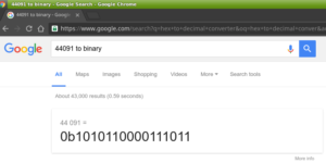
The binary value 1010110000111011 (commonly written as 0b1010110000111011 or 1010110000111011b) is equivalent to hex value AC3B (commonly written as 0xAC3B, or AC3Bh)

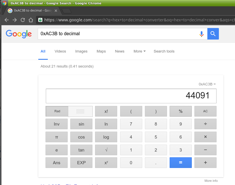
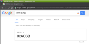
To convert to decimal, the value 0xAC3B can be viewed as:

|---16^3
||----16^2
|||-----16^1
||||------16^0
AC3B

where the number has

("A" *16^3) + ("C" *16^2) + (3 *16^1) + ("B" *16^0), or 
(10  *4096) + (12  * 256) + (3 *  16) + (11  *   1)  == 44091 dec.

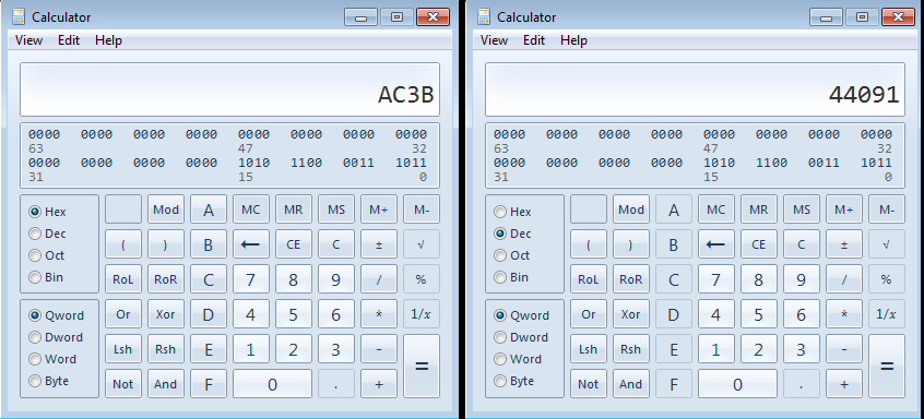
As with base-10 math, there are calculators available that aid in converting numerical representation.

On Windows, the “calc.exe” in programmer mode (View->Programmer) is handy:

calc

You can also try the Google:

Screenshot - 07222016 - 10:39:37 PM Screenshot - 07222016 - 10:40:06 PM Screenshot - 07222016 - 10:40:21 PM

As a building block in software and embedded systems development, having a working knowledge of these three numerical systems are a prerequisite.  There is another format, Octal, that’s base-8, that is usually also introduced in Computer Science.  I think after going through binary and hex it isn’t to hard to figure out.